Routing in case of extensions
In a number of case, the use of an extension will have an impact on the routing. In this page, these impacts will be discussed.
Definitions
Routing maps can be defined in rivers, conductive buffer dams and conductive ditches, see here. In these routing maps specific routing directions can be defined,
A buffer is not the same as a conductive buffer dam as buffers are defined as a buffers with a buffer properties, whereas conductive buffer dams are defined as one-target routing paths. As such, it is up to the user to define a buffer measure as a buffer (with properties such as a trapping efficiency) (1) or a conductive buffer dam (with a routing raster) (2).
Routing in buffers, conductive ditches and conductive buffer dams
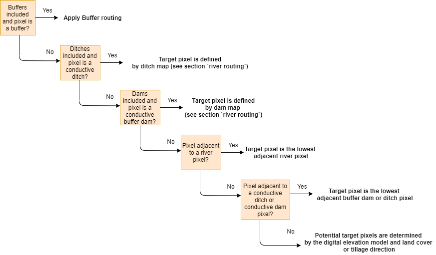
The routing algorithm is adapted according to extensions that can be used in WS, such as buffers, conductive ditches or conductive buffer dams These exceptions are described in the figure below. There is only one target pixel if a pixel is a conductive ditch, conductive buffer dam or adjacent to a conductive ditch, conductive buffer dam or river. Note that the routing in conductive ditches and conductive buffer dams always routes to the lowest conductive ditch and conductive buffer dam pixel. Routing to the lowest conductive ditches and conductive buffer dam pixel can only be accepted from conductive ditches and conductive buffer dam pixels to avoid looped routing.

Flow-chart of the routing algorithm in WaTEM/SEDEM describing the method in case buffers, conductive ditches and conductive buffer dams are used.
If the source pixel is a buffer pixel then two cases are defined:
The considered pixel has a buffer_id. This is the outlet pixel of the buffer. The default routing algorithm is used in this pixel. Note that only routing from extension-id pixel can be accepted to avoid looped routing.
The considered pixel has a buffer extension-id. In this case there is only one target pixel: the pixel within the buffer with the buffer_id (i.e. the outlet of the buffer).
We refer to the section on buffers for a complete description of how buffers are defined. For description on the definition of conductive buffer dams and conductive ditches, we refer to the section on routing maps.
In the second part of the default routing algorithm, two target routing is defined (see section two target routing).
Adjustment upstream area and outflux
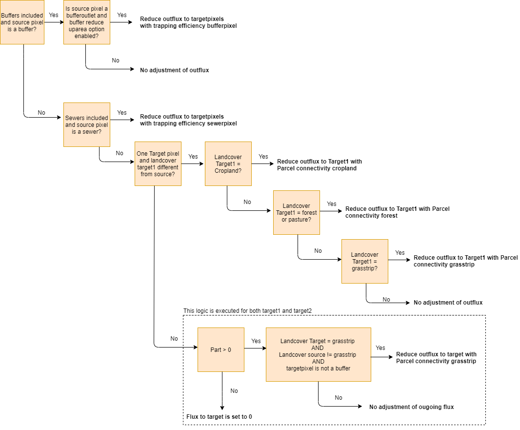
In some special cases the outflux is reduced (for example in buffer outlets, sewers or when the landcover of a target pixel is different from the source pixel). The flow-chart below clarifies in which cases the reductions on the upstream area are applied in the calculation of the outflux.

Flow-chart of the distribution of the outflux of a pixel in WaTEM/SEDEM. Part is the fraction of the tabulated outflux. Note that the sum of Part to target1 (part1) and target2 (part2) is equal to 1.
When the outflux is known for a source pixel, this flux is added to the influx of the target pixels by (note that part1+part2 = 1)
with:
\(\text{influx}_{\text{target1}}\): the influx of the first target 1 pixel. +: posterior, -: priori.
\(\text{influx}_{\text{target2}}\): the influx of the first target 2 pixel. +: posterior, -: priori.
\(\text{outflux}\): the outflux of the source pixel.
\(\text{part1}\): the fraction of the routing from the source pixel to the first target pixel (-).
\(\text{part2}\): the fraction of the routing from the source pixel to the second target pixel (-).
Forced routing
Forced routing is typically used to force a routing vector from a specific source to a target pixel, in case of a local suboptimal routing pattern. Forced routing is user-defined. The instructions for defining forced routing are found here.
Routing maps
Routing maps maps are used to define routing in rivers, conductive buffer dams and conductive ditches. We refer to separate sections for the definition of routing in rivers, ditches and dams. The workflow on how to create these rasters is described in the section on routing maps.