Routing
The flow and sediment routing is based on a multiple flow direction algorithm implemented on a fixed grid. Specifically, the algorithm makes use of the height profile and class of land cover to define the flow from a source pixel to one or two target pixel(s).
The flow routing varies as a function of the difference in height between the source and potential target pixels, and the land cover class of the source and targets. In addition, it varies as a function of presence of conductive dams, conductive ditches and buffers (and forced routing, see here). The land cover is defined in the following table (see also here). The codes (pixel id) listed in this table are used to define the routing in WaTEM/SEDEM. An important distinction is made between the land cover of (a) target(s) being equal to the class river (-1) and not being equal to the class river (non-river pixels). Do note that in this manual the non-river pixels are sometimes referred to as land pixels.
Land cover/use class |
pixel id |
|---|---|
agricultural fields |
> 0 |
outside model domain |
0 |
river |
-1 |
infrastructure |
-2 |
forest |
-3 |
pasture |
-4 |
open water |
-5 |
grass strips |
-6 |
Definitions
Routing flows from land to land pixels, land to river pixels, river to river pixels, but not from river to land pixels!
The cardinal direction is defined by the four main compass directions, north, east, south and west. Cardinal pixels are defined by the four neighbouring pixels of the source pixel in the cardinal directions.
The ordinal (or intercardinal) direction is defined by the northeast, southeast, southwest and northwest direction. Ordinal pixels are defined by the four neighbouring pixels of the source pixel in the ordinal directions.
Adjacent pixels are defined by the eight neighbouring pixels of the source pixel.
One-target routing is defined in the cardinal and ordinal directions (and any direction in between for jumps) while two-target routing is defined only by the cardinal direction.
Flow scheme of the routing algorithm
In this section we will describe the routing algorithm in depth, with several flow charts as an illustration.
The first step of the routing algorithm is to sort all pixels in the raster from high to low, based on the digital elevation model. In the next step, the algorithm loops over all pixels, starting from the highest pixel:
If the pixel is a land pixel, the default routing algorithm is used. If the user enables the Forced Routing-option in the ini-file, the calculation of the routing by the default routing algorithm is altered on user-defined pixels. Thus, for these pixels, the user-defined routing will overrule the rulebank of the routing algorithm. This is an extension (see here)
If the pixel is a river pixel and the river routing option is enabled (see here), the algorithm will use the user-defined routing in the rivers. If the pixel is a river pixel and the river routing is not enabled, than no river routing is calculated. This is an extension (see here)
If the landcover of a pixel has a value of 0, it is skipped and no routing is calculated for this pixel.
One- and two-target routing
Routing over land pixels can be defined as two- (cardinal directions) or one-target (ordinal and cardinal directions) routing.
Two targets: routing is defined by one or two targets as a function of the direction, this only in the cardinal direction, thus only considering four cardinal pixels. Flows and sediment loads are distributed according to the angle between the direction (float number between 0 and 360 degrees) and the cardinal axes (see section two target routing). This direction is determined by the digital elevation model (and if relevant the tillage direction).
One target: routing is defined by one routing vector, and can be in the cardinal and ordinal direction, thus eight adjacent pixels. One-target routing is based on a decision tree (see figure section one-target routing) using land cover and the digital elevation model. The starting point for one-target routing is the two-target routing.
Two-target routing is computed first based on the digital elevation model (and the tillage direction, extension). This two-target routing can still be changed to one-target routing based on the land cover of the targets (see section one-target routing). Note that the digital elevation information is still used in the one-target routing scheme (in case of jumps).
Two-target routing
If the routing is not determined by a buffer, conductive ditch, conductive buffer dam or a river, the routing algorithm checks whether the flow direction vector D is steered by the steepest descent direction (or the tillage direction, see here). The cardinal directions define the target1 and target2 pixels, and the weight (\(\in[0,1], \sum \text{weight} = 1\)) they receive from the source pixel. This amount can be used to weigh the sediment load per pixel (WaTEM/SEDEM), the direct run-off depth (Curve Number) and upstream area (WaTEM/SEDEM & Curve Number) for each target pixel (see next section).
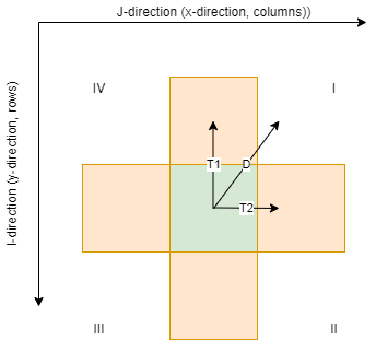
In the figure below it is shown how the two targets are determined by the routing direction vector D. The routing direction (determined by the height profile and - if included - the tillage direction) is first split in two cardinal directions (T1 and T2). Depending on the quadrant the direction points to, index shifts are defined for the raster, with one pixel in the x-direction (columns in rasters) and y-direction (rows in rasters) (see also table below). The index shifts are used to define the two target pixels. The amount of flow and sediment load that is routed to each of the two targets is calculated by computing the angle between the cardinal direction of the targets with the direction vector D (determined by height profile and -if included- the tillage direction).

Illustration of how two-target flow routing is determined. D = direction, T1 = Target1 (first clockwise target), T2 = Target2 (second clockwise target). I, II, III, IV = quadrant.
quadrant direction |
direction (degrees) |
i-index target 1 (y-direction) |
i-index target 2 (y-direction) |
j-index target 1 (x-direction) |
j-index target 2 (x-direction) |
|---|---|---|---|---|---|
I |
[0,90] |
-1 |
0 |
0 |
1 |
II |
]90,180[ |
0 |
1 |
1 |
0 |
III |
[180,270] |
1 |
0 |
0 |
-1 |
IV |
]270,360[ |
0 |
-1 |
-1 |
0 |
One-target routing
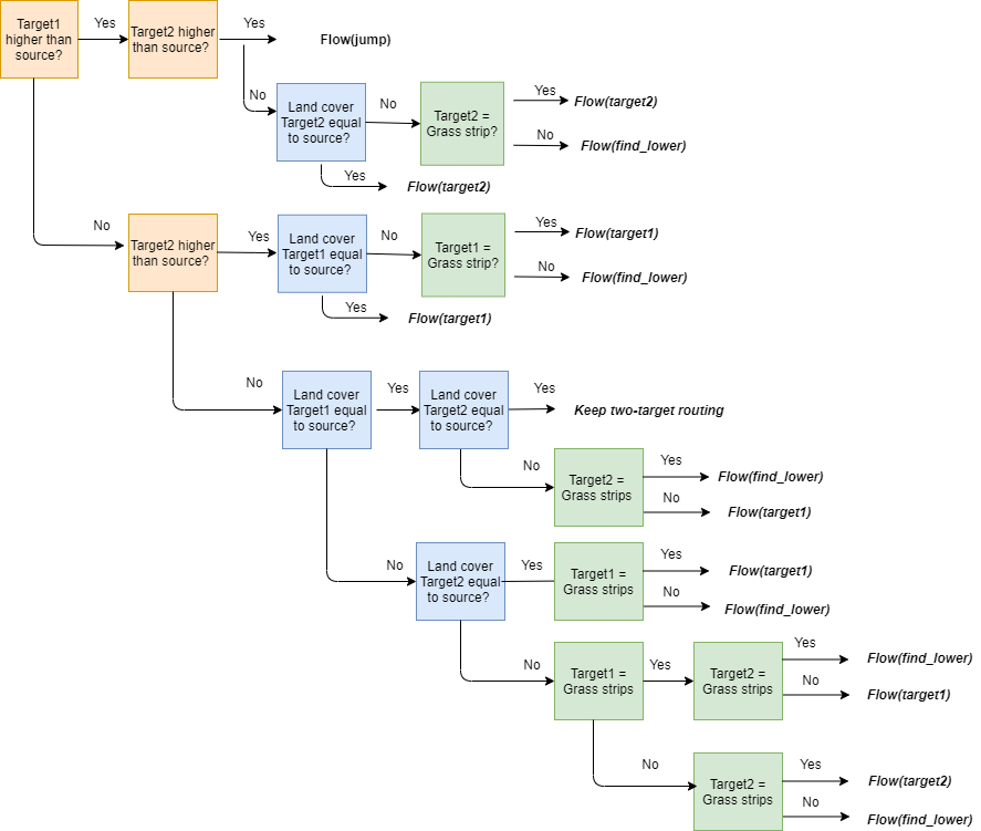
One-target routing is determined by the digital elevation model and the land cover of the two target pixels determined in the section above. The flow directions and weights (cardinal space) are adjusted according to elevation and land cover, as shown in the scheme below. Do note that in this procedure two-target routing is adjusted to one-target routing. Cardinal directions are maintained in this transformation, except for jump routing. By considering jumps, a wider range of pixels are considered. As a consequence, the direction is not solely defined by the cardinal and ordinal direction for jumps.

Flow-chart of the routing algorithm in WaTEM/SEDEM - adjusting routing according to elevation and land cover. This scheme adjust two-target routing to one-target routing. Note that the transformation of two-target to one-target routing will follow the cardinal directions, expect for the jumps. By considering jumps, a wider range of pixels are considered. As a consequence, the direction is not solely defined by the cardinal and ordinal direction for jumps.
In this figure, the Flow(target1) or Flow(target2) tag indicate that routing will follow strictly the path of the first or second flow direction. The find_lower tag indicates that the algorithm will search for the lowest neighbouring pixel: this functionality is used to indicate if a single target (cardinal and ordinal directions) is used instead of two targets (cardinal direction). A jump indicates the target is not a adjacent pixel of the source: the routing jumps to a single target further than its eights adjacent pixels. Jumps are defined within a window \(W\). This occurs when a source is located in a local elevation minimum. With increasing \(W\) more potential targets are considered, e.g. 16 for \(W\) = 2, 25 for \(W\) = 3, …
An important note is that the routing will always jump to the closest river in \(W\) if a river pixel is present in the window \(W\). This window \(W\) can be defined in the ini-file with the kernel - variable.
In the flow chart, three features of the source pixel and the two target pixels are accounted for to define a rule-bank for the routing direction: the elevation, the land cover code and the presence of grass strips. First, the elevation of the target pixels is examined in relation to the source pixel’s elevation. In case one of the target pixels is located at a higher elevation, the flow will be defined towards the other target based on the land cover code and presence of grass strips.
If the elevation of both target pixels is lower, the land cover code of the targets is checked. If they both have a different land cover code than that of the source, the find_lower-function is called. Additionally, if one or both have a different land cover code, it is checked whether the pixel(s) is/are (a) grass strip(s): in this case the flow direction will always be defined by the grass strips.
The implementation of this rule-bank aims to satisfy following conditions:
The routing should generally follow the height profile.
Routing within one agricultural parcel will remain in the parcel until the lowest point of the parcel is reached. Thus, the routing will follow the height profile in the direction of parcel boundaries rather than the steepest descent.
Routing should target grass strips as a priority target. An exception is defined if the two target pixels and the source pixel all have different land cover codes (with one target pixel being a grass strip), and the target grass strip being higher than the other target: here the routing follows the direction of to the lowest pixel.
Pixels next to a river always route to a river (unless an extension is used, see here)
Upstream area calculation
Once the routing is known, the upstream area for all pixels is calculated. A distinction is made between the influx and the upstream area for a pixel. The influx is defined as area of all pixels flowing into the considered pixel, not considering the contribution of the considered pixel itself to the area. The upstream area for a pixel is defined as the area of all pixels flowing into the considered pixel, including the area of considered pixel:
- with:
\(A\): the upstream area of the considered pixel (\(\text{m}^2\)).
\(\text{influx}_i\): the area of all pixels flowing into the considered pixel \(i\) (\(\text{m}^2\)).
\(a\): the pixel size (\(\text{m}^2\)).
\(PTEF\): the parcel trapping efficiency of a pixel.
\(n\): the number of source pixels. Note that only pixels are considered as source pixel in case they directly route to the target pixel.
The influx is defined as zero for all pixels that do not receive any flux from upstream pixels. These pixels are the first pixels treated in the WaTEM/SEDEM routing scheme. Their upstream area is equal to \(a \cdot (1-PTEF)\). The PTEF is defined by the user for cropland, pasture and forest.
Once the upstream area of a pixel is known, the outflux, or distribution of the upstream area to its target pixels, is calculated. By default this outflux is equal to the upstream area of the source pixel itself. Adjustments to this outflux can be done in case of using extensions (see here)